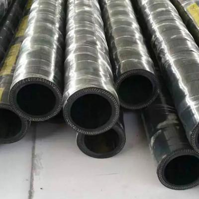
1、 Sandblasting hose And connector model
according to Sandblasting hose List the actual needs, and select the appropriate sandblasting hose model and sandblasting hose connector model
For example: 10-2SN * 3600 (24211-06-06/24291-06-06) sandblasting hose selection φ 10-2SN; One end sandblasting hose joint is 24211; 24291 at the other end
2. Determine the length of blanking rubber hose
Blanking hose length: the total hose length includes the length of the connectors at both ends of the hose. The actual blanking hose length should remove the length of the connectors at both ends.
3. Pipe cutting
The sandblasting hose is cut to the designed length according to its required specifications. The cut section shall be vertical and flat without damaging the steel wire layer.
4. Peel the outer glue layer
For the hose to be stripped of the outer rubber layer, the length of the outer rubber layer stripped at both ends of the hose shall be calculated according to the size of the sandblasting hose joint and the outer sleeve, and the position shall be marked with a marking pen. After rubber stripping, the steel wire shall not be damaged, and the inner wall of the hose shall not be damaged.
5. Mark the position where the sandblasting hose is inserted into the sandblasting hose connector
Place the hose beside the pipe joint, compare the insertion depth of the hose and mark it.
6. Rubber tube insertion connector
Apply a little hydraulic oil or lubricating oil on the inner core of the sandblasting hose connector, and insert the pipe into the connector until the marking line is flush with the end of the sleeve.
7. Angle setting
The space angle of the sandblasting hose assembly should be noted only when the pipe joints at both ends of the hose are bent joints and not in the same direction. (The angle of the sandblasting hose assembly is: the angle needed to turn the far end elbow clockwise to be consistent with the near end elbow is the angle of the hose assembly.)
8. Fastening hose assembly
Select the appropriate buckling mold to install on the buckling press, place the pipe joint to be buckled correctly in the buckling mold, press the buckling switch until all the molds are buckled on the pipe joint and run to the designated position in the attached parameter table. Loosen the clamping mold and take out the rubber hose assembly, check whether the clamping trace on the clamping surface is even, and use a vernier caliper to measure whether the clamping dimension is within the scope of the clamping dimension.

9. Clean and seal the hose
The hydraulic system must reach a certain degree of cleanliness. Use an efficient and convenient pressure cleaning device to clean the hose assembly. This device uses kerosene to wash the inner wall of the hose assembly, and then uses high-pressure gas to blow out the cleaning solution. The cleaned sandblasting hose is protected at both ends of the sandblasting hose assembly with a sealing cap or a sealing pocket.
10. Pressure detection
The sampling pressure test shall be carried out for the rubber hose. The pressure test shall be carried out on the pressure test bench. The pressure of the rubber hose assembly shall be increased to twice the predetermined working pressure, and the pressure holding time shall be 30-60 seconds. There shall be no leakage.
Sandblasting hose When crimping the joint, where can the crimping effectively prevent the joint from falling off?
If the burst pressure is more than 4 times of the working pressure specified in the standard, it is regarded as qualified hose.
If the blasting occurs at the buckling point, the main reason is that the rubber hose and the joint have not yet reached the coordination. The improvement should be mainly in the selection and buckling of the joint.
The compression capacity or material of the connector core needs to be improved. If the joint cannot be changed, try to reduce the amount of buckling without losing the joint, so as to avoid damage to the steel wire of the hose caused by excessive buckling.
Use of sand blasting hose assembly:
Used for mine hydraulic support, oilfield development, engineering construction, lifting and transportation, metallurgical forging, mining equipment, ships, injection molding machinery, agricultural machinery, various machine tools and mechanization of various industrial departments The automatic hydraulic system is used to transport petroleum based liquids (such as mineral oil, soluble oil, hydraulic oil, fuel oil, lubricating oil) and water-based liquids (such as emulsion, oil-water emulsion, water) with a certain pressure and temperature and liquid transmission pipelines.


